There are several versions of the Train Actuator Shield (TAS) but all work with a Sketch running in the attached Arduino Uno to act like a mechanical switch, turning on/off connected AC voltage (except the TAS Relay which can switch both AC & DC voltage). Features of each TAS version are described more fully in the TAS User Manual and Purchasing Catalog.
All versions of TAS are generic Arduino Uno Shields which can be used for anything you want (such as home automation). No trains are required. No TES is required.
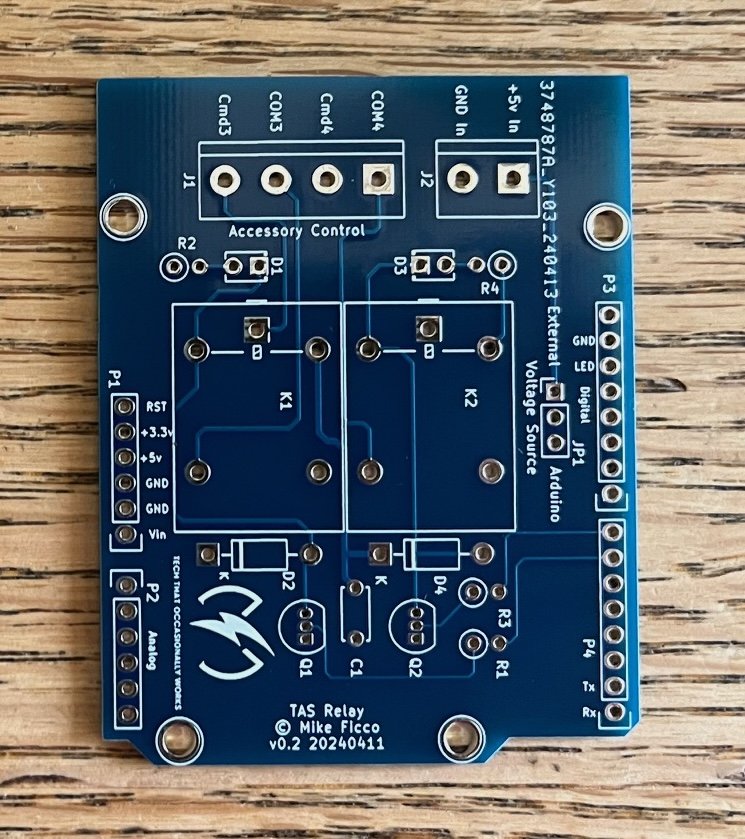
This version is the TAS Relay. This model of the TAS uses relays to switch the outputs, so unlike any other TAS, it can control both AC and DC voltage. The relays are rated at 10 amps, 250 volts AC and 10 amps, 30 volts DC. The relays are tall, projecting above the point where another Arduino Uno Shield could be placed on top because the standard pins would be too short. It must be the top Shield in a stack. It handles command signals on Arduino Uno digital pins 6 and 7. Also, actuating the relay coils consumes much more power than the triacs in the other TAS. See the TAS User Manual. The picture shows the jumper that can select the source of the power to the relay coils. If you plan to hold the relays on for several minutes you may want to use external power. I tested several Uno clones and they (and my TES) get warm after a few minutes. So, no problem for controlling an uncoupling track for a few seconds or to ignite a rocket fuse. Test carefully if you intend to have both relays engaged for a long time. The little Arduino is not intended to deliver that much sustained power.
All images should be considered representative. That is, the PCB or color may change and components, logo, whatever… may be added, removed, revised, or moved. What you receive may look different – but it will work as described.


