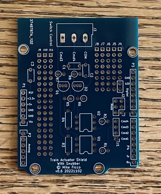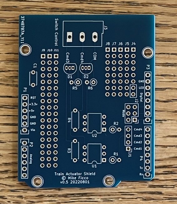
TAS Max
TAS (Train Actuator Shield) Max version
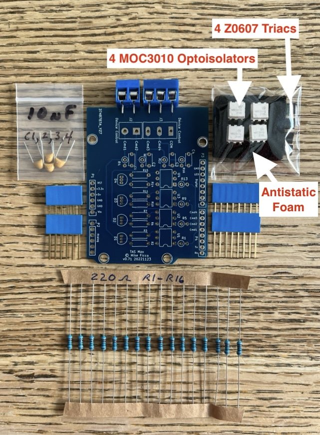
This model of the TAS has a built in "Snubber circuit" to improve the reliability when controlling somewhat inductive loads (like vintage Lionel animated accessories). It handles four command paths - signals on Arduino Uno digital pins 4, 5, 6, and 7 (Match Commands 1, 2, 3, & 4). No assembled version is available. You can get either the raw PCB or the complete kit.
TAS (Train Actuator Shield) Max version
This model of the TAS has a built in "Snubber circuit" to improve the reliability when controlling somewhat inductive loads (like vintage Lionel animated accessories). It handles four command paths - signals on Arduino Uno digital pins 4, 5, 6, and 7 (Match Commands 1, 2, 3, & 4). No assembled version is available. You can get either the raw PCB or the complete kit.
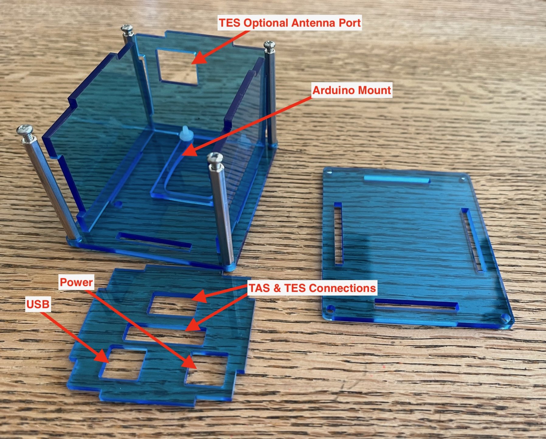
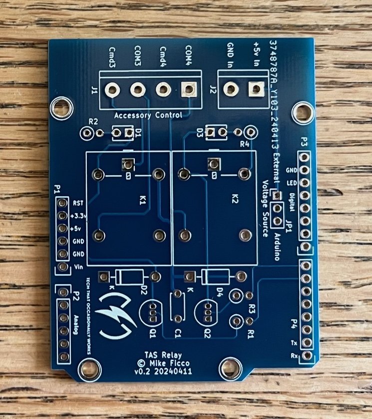
There are several versions of the Train Actuator Shield (TAS) but all work with a Sketch running in the attached Arduino Uno to act like a mechanical switch, turning on/off connected AC voltage (except the TAS Relay which can switch both AC & DC voltage). Features of each TAS version are described more fully in the TAS User Manual and Purchasing Catalog.
All versions of TAS are generic Arduino Uno Shields which can be used for anything you want (such as home automation). No trains are required. No TES is required.
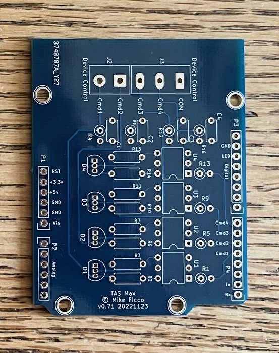
This version is the TAS Max. It has a built in "Snubber circuit" to improve the reliability when controlling somewhat inductive loads (like vintage Lionel animated accessories). It replaces the prototyping area with additional circuitry allowing it to respond to two extra command paths. That is, the Sketch can send command signals on Arduino Uno digital pins 4, 5, 6, and 7.
All images should be considered representative. That is, the PCB or color may change and components, logo, whatever… may be added, removed, revised, or moved. What you receive may look different – but it will work as described.